Author’s update March 27, 2013:
I was finally able to try the method against unfired brass in a wildcat based on the 6.5 Grendel. The brass was Hornady and the expected pressures per QuickLoad® ran from about 46,000 psi through about 56,000 psi. The change in base diameter was less than .0005″ in all instances.
One possible explanation is that this brand of brass is harder than the brass modeled in VarmintAl’s calculation.
More tests are needed to determine the validity of the method.
******
Most of us reloaders stay well within the boundaries defined by commercial load data. This important safety practice costs very little in terms of real performance in the field. Test this by using your favorite ballistics calculator to estimate the drop for the starting load (typically 5-10% below max) and the maximum load at 300 yards. Then compare that to the holdover, if any, you might need to get the bullet inside the canonical 10” vital zone. The bottom line is that even though the starting load drops a bit more, it won’t normally make a big difference in your sight picture at customary hunting ranges. Similarly, the bullet’s lethality is very close to the same at both the starting and the maximum loads.
This very safe practice gets stressed, however, when a new powder or bullet appears on the market. Unless you happen to shoot one of the popular calibers the powder and bullet companies target their powder for, you will wait a long time before you can get commercially vetted load data. Similarly, long-range target shooters frequently press the maximum load ceiling to get the slight added performance edge that can make the difference between winning or losing a contest. How do you work up safe loads when you happen to be in one or both of these groups?
The answer to this question is divided into four parts. The first part gives a basic procedure for using cartridge case head expansion. The second part is a thumbnail sketch of methods used by commercial houses to assure compliance with SAAMI standards. The third part is a more comprehensive method for using case head expansion to detect when pressures are getting too high. The fourth and last part describes the results of a series of engineering calculations that suggest the method is viable.
— An Easy Test —
A lot of folks use the classic primer inspection, loose primer, smearing of case head into bolt face, and so on to get a feel when their loads are a tad on the hot side. Even though some controversy exists regarding reliability, the general assumption is that these signs start to become evident when pressures exceed something like 55,000 psi and become clearly obvious at above 63,000 psi. The reader must interpret for himself what is meant by “evident” and “clearly obvious” since a fair amount of judgement is needed to make use of these techniques.
Perhaps the most accurate pressure sensing systems available to the handloader are strain gauge – based systems like the Pressure Trace System by Recreational Software, Inc. These systems unfortunately cost as much as many of the rifles we use. The significant cost combined with the challenges of using the systems correctly place them more or less out of reach of the average handloader.

Measure the diameter at the web
Case head expansion uses less sophisticated equipment and is a tool one can add to the set of things to check when trying to infer pressure levels. In brief, one measures the change in diameter of the case at the head – between the extraction groove and the main cavity of the case. Interestingly, we are doing a measurement that is analgous to, but not the same as, the the change in length of crusher cylinders classically used by industry.
The anvils of standard micrometers tend to be large enough1,2 that one tends to get the pressure ring rather than the base diameter measurement. As the illustration above suggests, a blade micrometer is the best tool for this measurement but they tend to cost nearly as much as the strain gauge pressure trace system. This leaves standard calipers as the remaining measurement tools – and these have blades!
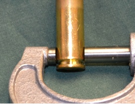
The micrometer anvil is too large to measure the case head diameter. It bridges either to the rim or the pressure ring
Calipers, of course are accurate to the nearest mil (0.001 inch) meaning that we will need to see more than one-half mil expansion to detect any increase in diameter.
Here’s what we do:
- Measure and record the diameter of several factory loads or trusted handloads with headstamp always in the same position.
- Take the average of these measurements.
- Shoot these cartridges recording all relevant information as usual.
- Measure the new case head diameters using the same technique as above.
- Take the average.
- Subtract the average unfired diameter from the average diameter of the now once-fired cases.
This average change in diameter gives a baseline for your brass and your rifle.
The next step also needs to be done with unfired brass and must be the same brand of brass that you used to establish the baseline. Do the same before and after measurements for the loads you develop while keeping the brass sorted by charge weight, bullet, etc. The change in diameter should be the same as or less than your baseline. If larger, then you should strongly consider reducing your load.
I developed an example baseline using nine Remington .243 Winchester 100 grain factory Core-Lokt® rounds. The average case head expansion measured with the dial caliper was between 0.0015 and 0.0025 inches. We compare this with the expansions calculated by VarmintAl (See the last two images in this paper.) and find that this factory load has an expansion very close to his calculation for the SAAMI maximum pressure for the .243 Winchester.
While it appears that this brass was a little softer than the material VarmintAl modeled, we would have been astounded if there had been a closer correlation. VarmintAl modeled generic cartridge brass while each manufacturer uses a unique processing schedule and gets brass stock from different sources. The strengths are different for each brand and even for each lot. This is why one needs to baseline using the same brand, preferably the same batch, of unfired brass for baseline and load work up when using this method.
The method may not work for you, but the same can be said of reading primers and brass smears. Try it and see if it works! If it does, then you can add it to the other techniques you use to tell if the loads are getting close to doing bad things to your rifle.
The remaining notes in this section expand the discussion of pressure sensing in rifles, adds a more detailed process to use when one does a ladder or Optimal Charge Weight test, and concludes with a discussion of why the case head expansion technique can work. The detail adds up but the principles are the same as we have already discussed.
— Pressure Testing by Commercial Manufacturers —
Many of our commercial reloading data sources use dedicated pressure testing rifles or pistols to get pressure data through a standard form. One of the primary motivations for this testing is to demonstrate compliance with SAAMI guidelines. Reloading data are no different – the powder or bullet manufacturer is motivated to show that his loads are safe.
Pressure detection in the commercial laboratory can be by one of these three methods:
- crusher cylinders,
- piezo crystals,
- strain gauge.
Calibrating piezo and strain gauge data with crusher cylinder results is extraordinarily difficult other than in generic terms because the phenomena being tracked are different. Shortening of the crush cylinder takes a finite time so the change in length is influenced by the integral of the pressure history. Further, the shortening is influenced by strain hardening and strain rate effects of the copper or other standard metal during the time the high pressures are being applied.
Unlike the strain gauge method, the crystal is directly exposed to the powder gases. Couple this direct exposure to the very short response time of the crystal and we can see that this method more accurately captures the peak pressure.
The strain gauge method consists of placing strain gauges on the outside of the breech. While the gauges also have very fast response times, they depend on the response of the breech to the pressure pulse. So, while the pressure history and peak pressures obtained with this method will be very close to the piezo method, they are unlikely to be identical.
All three methods, however, produce useful results for demonstrating SAAMI compliance and promoting handloading safety.
— Judging ‘safe pressures’ by the Handloader —
Handloaders are generally constrained to less resource-intensive methods than commercial shops for confirming that pressures are within reasonable levels. We often see these techniques discussed:
- primer flattening and or cratering,
- loose primers,
- gas leakage around primer pocket,
- blown primers,
- difficult extraction (hard to detect with semi-automatics),
- case head expansion,
- strain gage.
All of the methods available to the handloader experience some degree of controversy. See, for example:
and
The truth about ‘pressure signs’
The concerns expressed are valid. Of these, only the strain gauge method comes close to mapping into commercial load databases but the cost of the equipment and related hardware is normally several hundred dollars.
As a result, a large number of serious handloaders continue to use the older methods because they represent the only tools available for detecting an approach to significantly high pressures. The case head expansion technique can be useful for the careful and knowledgeable hand loader. Let’s take a closer look.
The first step is to acknowledge the rebuttal of Ken Water’s “Pressure Ring” method by Bramwell (PRE, CHE, RIP). Ken Waters method measures the change in diameter just above the web of the base where the brass is a little thicker than the rest of the case wall. This is not a location that produces behavior that is analogous to the copper crusher cylinder. Bramwell’s rebuttal, while accurately critical of the pressure ring method, does not address the case head expansion technique.
Furthermore, gas-operated firearms like those in the AR family frequently allow the case to start extracting while some pressure remains in the chamber. The resulting rings look like Water’s pressure rings but are meaningless in the context of pressure measurement. We are still able to use case head expansion, however, because that part of the case is not supported by the chamber, so the timing of the action opening cycle is less critical.
Let’s turn to a discussion of about how to do the measurements in a way that parallels the commercial laboratory crusher cylinder method. Unlike the crusher cylinder, this method works in your chamber and does not result in a pressure estimate. The method instead generates a picture of the behavior of your brass in your chamber. You will also invest 20 or more rounds of trigger time plus a little chronograph work provided you have one.
Reader beware: Validating this method is more in your hands than one might first think. The method asks that you first calibrate against factory ammunition or known handloads with the same lot of unfired brass you plan to use for your ladder test3 or round robin4 series. Second, the method also asks you to draw up a scatter plot showing the head expansion for each of the shots you made in the ladder test. You will do something similar with the impacts on the target so it is a small extension of what you already do. You will be able to get a good idea of whether the data are meaningful by a quick perusal of the plot. The points do not need to appear to be in a neat line, but you do want to see a discernible trend.
If you don’t get what appears to be a recognizable trend, two things are possible. First, the measurements may have been taken too high on the case and you were actually measuring the pressure ring expansions. The second possibility is that you were measuring the rim diameter. It is also possible that the method doesn’t work for you.
THE METHOD Step 1: Establish a Baseline for Your Rifle and Brass —
Build the baselines5 using a known load in unfired brass from the same lot as what you plan to use for developing your loads. You can also use factory loads in the same brand. Plan to shoot at least five of these loads, preferably over a chronograph, to establish your baseline expansion.
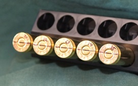
Scribe a line across the case heads and number them for future reference.
- Use a fine line permanent marker to scribe a reference line across the bases.
- Number the cases for reference.
- Measure the diameter in the direction defined by the line and record by case number.
- Shoot the factory ammo or trusted handloads and repeat the measurement & recording.
- Subtract the unfired diameter from the diameter of the now once fired case. Use the case number to make sure the measurements are consistent.
- Note the scatter and average of your case head expansions.
You can now use the extreme spread and average of your baseline head expansion tests as a reference for your load development.
THE METHOD Step 2: Make a scatter plot from your ladder or OCW test results —
- Use a fine line permanent marker to scribe a reference line across the bases of the loads you plan to use. (ALWAYS USE UNFIRED BRASS5 — fired brass gets work-hardened, and generates reduced expansion for the same pressure. This does not err on the side of safety.)
- Number the cases for reference.
- Measure the diameter in the direction defined by the line and record by case number.
- Shoot the ladder or OCW test, recording the normal information.
- Measure the new case head diameters using the same technique as above.
- Subtract the unfired diameter from the diameter of the now once fired case. Use the case number to make sure the measurements are consistent.
- Create a scatter plot of the differences in case head diameter versus charge weight.
- Compare the plot with the average and scatter of your reference loads (factory or known safe reloads).
This approach will not yield specific pressure data, but you can get an idea of trends and generic relative pressures. Most importantly, you develop a better understanding of how your brass behaves in your chamber.
Many users of the scatter test compare plots of velocity vs charge weight in addition to plots of impact height versus charge weight. Adding a plot of case head expansion versus charge weight may help add more insight into your search for one or more sweet spots. Similarly, the careful handloader will continue looking for all of the customary signs of serious pressure as a continuing double check.
— Why Parametric Case Head Expansion Can Work —
VarmintAl did a series of calculations using LS-DYNA, a well-established finite element code for exploring dynamic behavior of the bolt and case during a shot. One series of calculations looked at case head expansion.
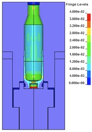
Cross-section of case in typical .243 Winchester chamber showing fringes of plastic strain at the peak pressure of 57,400 psi.
He applied a typical chamber pressure-time history to the inside of a cartridge case in a rifle chamber with the bolt in place. The pressure pushes the case back on the bolt face so the only way the brass can go is out where its diameter is smaller than the chamber. Our attention is on the small length of the case head just above the extraction groove.
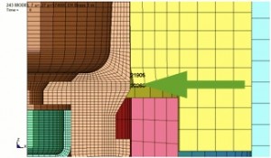
The green arrow is about where VarmintAl tracked the expansion. This area has the most brass and is not supported by the case wall. Expansion at this location is a rough analog to crush cylinder behavior.
The green arrow is about where VarmintAl tracked the expansion. This area has the most brass and is not supported by the case wall. Expansion at this location is a rough analog to crush cylinder behavior.
You can see from the illustration that the case head is not supported here. The lack of support allows the brass to expand in response to the dynamic pressure inside the case. Fortunately our safe loads are designed so that this expansion is not readily seen by the naked eye. Indeed, if you can see it, you have dangerously high pressures!
The head expands first elastically, meaning that, for very low pressures, the case head returns to the original diameter. As the pressure increases, however, we get plastic strain on top of the elastic, resulting in a permanent change of diameter. The amount the head expands depends both on the magnitude and duration of the pressure above the brass yield strength. We use precision calipers to measure this tiny residual change in diameter since we can’t see it.
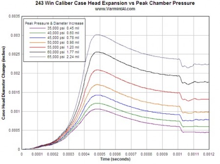
Time histories of case head diameter for a .243 Winchester for various peak pressures.
The calculated permanent set is the residual strain seen at the right-hand side of the time history plot. QuickLoad was used to determine how much Ramshot Hunter™ would be needed to get VarmintAl’s peak pressures for a typical bullet in the .243 Winchester. Then the permanent set of the results shown above was plotted against the powder needed to get the peak pressure. The permanent set as a function of powder charge is shown in the scatter plot.
The starting load for this powder and bullet combination is 41.0 grains per the Ramshot Load Guide Edition 4.4© while the maximum load is shown as 45.5 grains of Hunter™. The start load appears to be in a region where not much plasticity happens. The maximum load appears to have enough pressure that the brass is starting to move more rapidly suggesting significant reductions in case life and safety when more than the maximum recommended amount of powder is used.
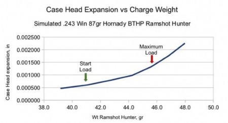
Simulated trend line for case head expansion.
| Plot YOUR own trend line even though some handloaders use 1 mil for 30-30 pressures and 1.5 mil for modern rifles. This way you will have data relevant for YOUR rifle and brass! |
Using fired cases for this exercise is a losing proposition because expansion from previous shots work hardens the brass, giving less expansion for the same pressure levels. Also note that the factory reference loads are just that: reference loads. The baseline works when the brass hardness is the same for both them and your brass.
There is no guarantee, however, that the factory loads will have the same brass6 as your unfired brass, but it is the closest we can get. The uncertainty underscores the reason for looking at a series of charge weights – we are looking for the region where the brass flow accelerates as a back-up to getting the same strain as the factory load.
Footnotes:
1 It is also possible to file shallow (not more than .002″) flats on the rim of most “rimless” cartridges to allow the anvil to seat properly on the base. While this might compromise the ability of the extractor to remove the case from the chamber, it will also be a marker for repeatable orientation on the case.
2One of the reviewers suggested that there is a cheap way to get the measurement with a precision micrometer that reads in tenths. Several companies make snap on balls [basically a ball bearing of about 0.250 in a cage] that fit over the anvils of a standard micrometer. With the balls in place one gets a point contact on the case rather than the l line contact. One has to be careful in making the reading as you are measuring a point not and not using a blade as with a caliper, but it works pretty well. You just have to move the mic back and fourth to make sure you get the true diameter of the case.
3 Review this pdf for a description of the ladder test: http://www.desertsharpshooters.com/manuals/incredload.pdf
4 Here is a description of the Optimal Charge Weight (OCW) method: Optimal Charge Weight
5 Many wildcat cartridges need to be fireformed to be useable. Once-fired brass may be useful in this event provided that one uses the same recipe is used when forming the brass to be used in this testing. At the risk of sounding pedantic, remember that the test cases need to have been fired the same number of times as those used for the baseline.
6 Another reviewer suggested that one pull the bullet and powder from part of a box of factory loads and then replace with your load. For example, keep five rounds from a box intact to build your baseline, then pull and reload the remaining fifteen with your loads.
| Navigation — |
|---|
| Up to: The ‘Articles’ Section |
| Up to: ShootersNotes.com |
ACKNOWLEDGEMENTS
The author is deeply indebted to VarmintAl.com for giving permission to use the results of a calculation that is a rather strong example of why the method can work. He also provided significant constructive criticism along with Craig Eagle, Dick Hatfield, Greg Luli, Paul Scott and Todd Slavik for critical reviews. AmmoGuide’s tloc54 provided an excellent review of the first web version of the four notes. These reviews enabled the writing of a more readable and complete discussion.
I have certainly discussed this topic with others, and may have overlooked a name or two. If you have helped, please remind me and I’ll be happy to update this paragraph.

 sending...